The last few years have seen a revival of isometric graphics. Even with someone who is not familiar with the term ‘isometric’, chances are that they have encountered isometric illustrations in video games, logos, magazines or marketing materials.
At TDL we are seeing an increasing number of requests for isometric graphics – not necessarily as a branding tool but as means to communicate complex information. In this blogpost, we are going to examine the role of isometric graphics in our projects and advantages and challenges that come with them. Through reflection on our own experience, we would like to share what we have learned so far from working with isometric graphics in complex projects.
What is isometric?
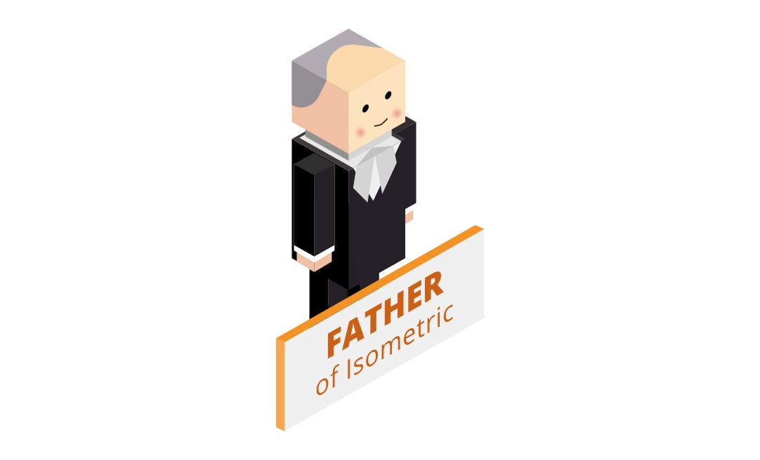
An isometric graphic is a method to represent a three-dimensional object on a two-dimensional surface by showing depth. Among several methods to achieve the same effect, isometric is unique in its schematic look and flexibility in the artwork. Isometric graphics became common features in our day-to-day life through video games in the 80s but they have a long history. The technique was developed by a British scientist William Farish (1759–1837) to illustrate the mechanical principles of machinery (1). It has been a useful tool for engineers and architects ever since. Unlike their ancestors and contemporary cousins in technical drawings isometric graphics these days have a very friendly look and feel — perhaps because they have adopted the style from much loved flat icons.
Technical bit
There are many blogs and online resources explaining what isometric graphics are. Wikipedia defines isometric projection as follows (2):
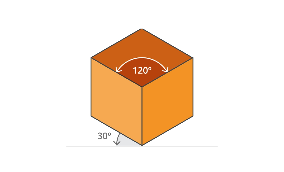
‘An isometric view of an object can be obtained by choosing the viewing direction such that the angles between the projections of the x, y, and z axes are all the same, or 120°… Note that with the cube (see image) the perimeter of the resulting 2D drawing is a perfect regular hexagon: all the black lines have equal length and all the cube’s faces are the same area.’
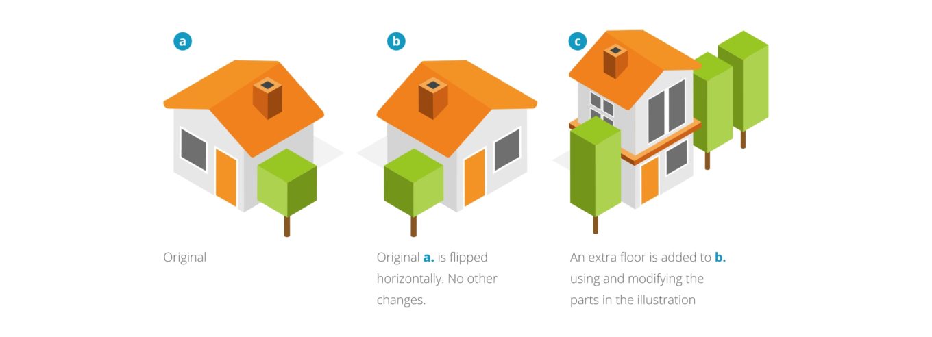
Unless you are creating isometric illustrations, it is not crucial to understanding how it works. It is perhaps useful to note from this definition though that, because the angles are all standardised, isometric graphics are versatile. They are easy to scale and easy to rearrange. For example, it can be a designer’s nightmare to be asked to flip an image, especially if it’s a complex 3D illustration. With isometric, flipping an image is relatively straightforward as all the elements in the illustration follow the same rules. This adaptability makes isometric illustrations a useful tool in information design as projects tend to go through numerous iterations involving rearranging the text and visual elements in the layout.

Benefits of isometric graphics
Comparing with 2D illustrations, isometric graphics in general require more time and care from both the client and designers. Nevertheless, they have been seen increasingly over the last few years. We think there are not only aesthetic but functional reasons to their popularity. Here are some benefits we have found from working with isometric graphics:
- Suited for illustrating complex information
- Easy to customise which means easy to create a bespoke look according to the existing brand guidelines
- Great scene creators
- Engaging to look at and work with
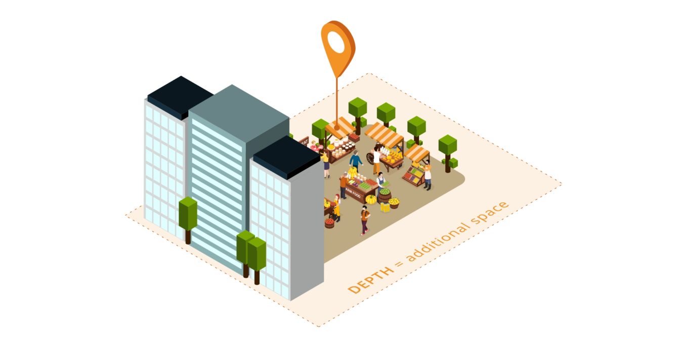
The first point is important when we are working on a project involving a lot of information. Similar to any other 3D projections, isometric adds another dimension and depth to graphics, this means they can hold more information than their 2D counterparts. In addition, the friendly schematic style of isometric graphics makes complex content more appealing and accessible for the audience. At TDL we typically use isometric graphics in these areas:
- Hero diagrams (or ‘rich pictures’) to provide an overall understanding of key subject matter
- Process diagrams
- Technical drawings to show structures, design details and so on
- Instructions
- Floor plans
Our work examples are included in the project examples section below.
Things to be considered
Is it necessary? If so, how should it be used? Is there enough time to produce?
Isometric graphics are both charming and powerful, but they could also be overwhelming and confusing for some subjects and audiences. For instance, using the isometric projection in maps could confuse the users because of its fixed angle. Creating any illustration takes time, so it’s a useful exercise to first examine whether the isometric graphics are suitable for a given task and audience, then confirm if there is enough time to create them.
Planning ahead
Although they are relatively straightforward to modify, working with isometric graphics could be laborious especially when they are complex. Having detailed briefs at the beginning of the project, listing the purpose of the graphic, items to be included, and specifications for each item, is very useful. It makes the creative process smooth and efficient for everyone involved in the project.
Mix and match
Large scale projects often include a variety of graphic assets such as icons, illustrations, infographics and diagrams. When isometric graphics are part of a graphic suit, it is important to consider how they will work together with other types of visual elements including any accompanying text, while maintaining a coherent look and feel. There should be a system that works throughout the project.

Work examples
Isometric illustrations to explain ‘how to’
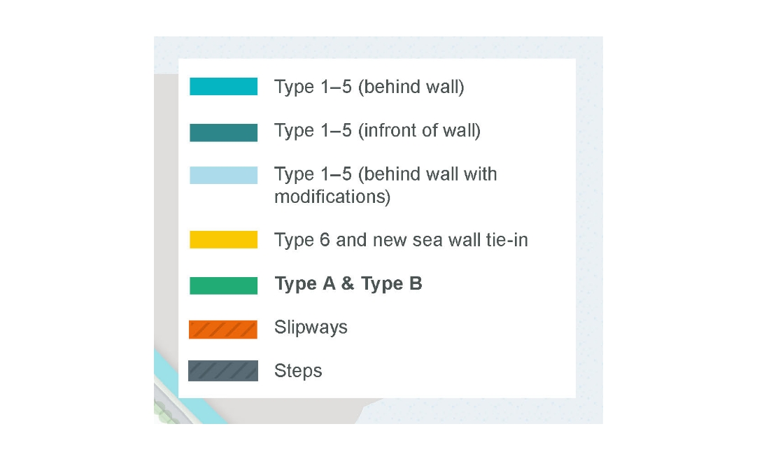
These examples demonstrate how the isometric illustrations and the text can work together to communicate complex information effectively. In figure 1, the isometric graphics were used to visualise a construction sequence of seawalls. Each stage is accompanied by a concise step by step description of the process. The colour coding in the illustrations is linked to the map on the left, setting the construction sites in the real-world context. Figure 2 works in a similar way. The bird’s eye view on the left, with the isometric projection layered on top, enables the reader to see the project in the actual environment.
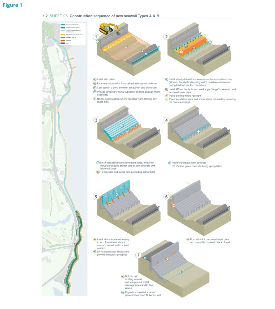
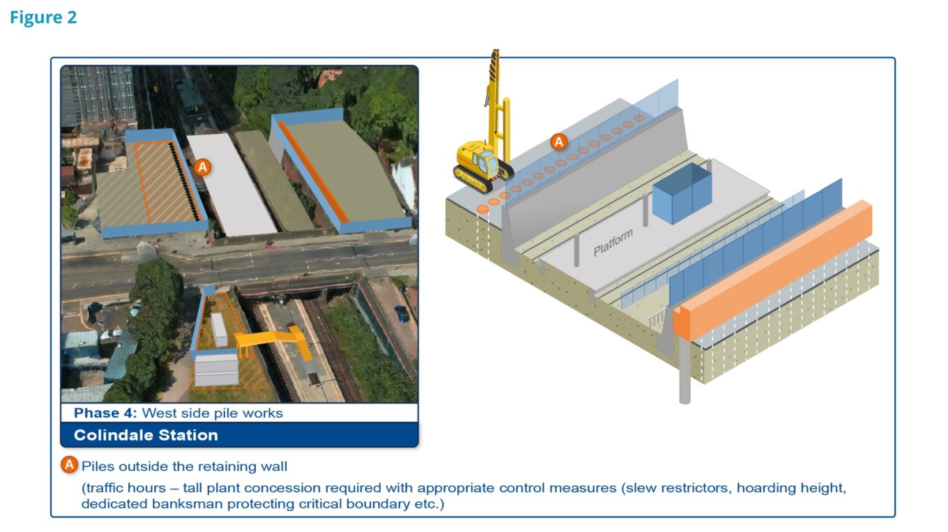
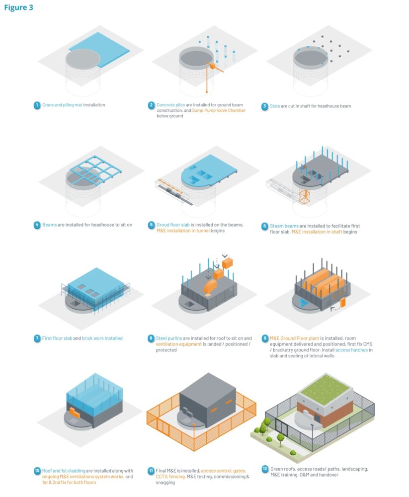
Figure 3 is a classic example of isometric illustrations visualising a process – in this case for a building project. These illustrations were all re-drawn from section and plan drawings.
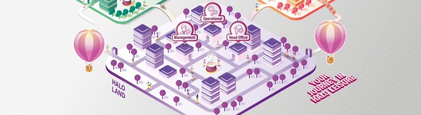
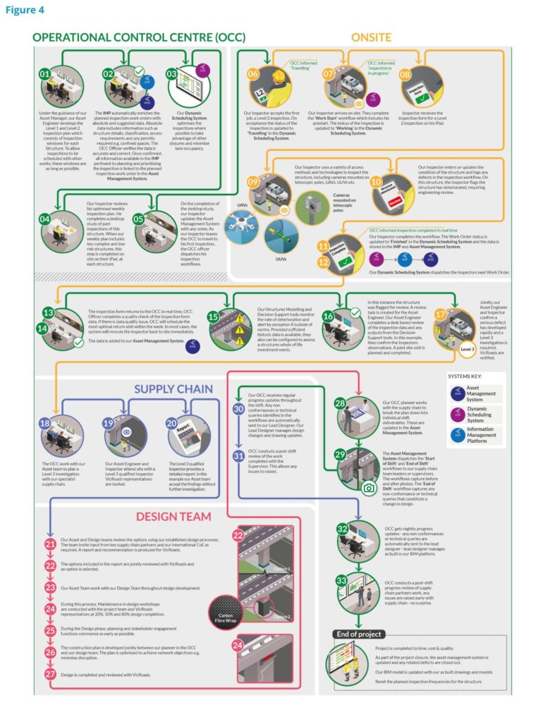
Isometric illustrations to explain tasks
Using isometric graphics in a diagram can present unique challenges as they tend to take up space and can be too detailed to appear clearly in small scale, especially if used in a page-limited bid document. In this example, the isometric illustrations are parts of a complex diagram explaining who is doing what along the way. The clear, simple structure and colour coding are essential in this flowchart. The isometric illustrations work as both explainers and bookmarks giving visual cues, and being placed in colour-coded circles their size is standardised to make the most of the limited space available.
Isometric illustrations to explain a concept
Using isometric illustrations is a great way of visualising a concept, especially when relating to a physical space or technology which does not yet exist in the real world.
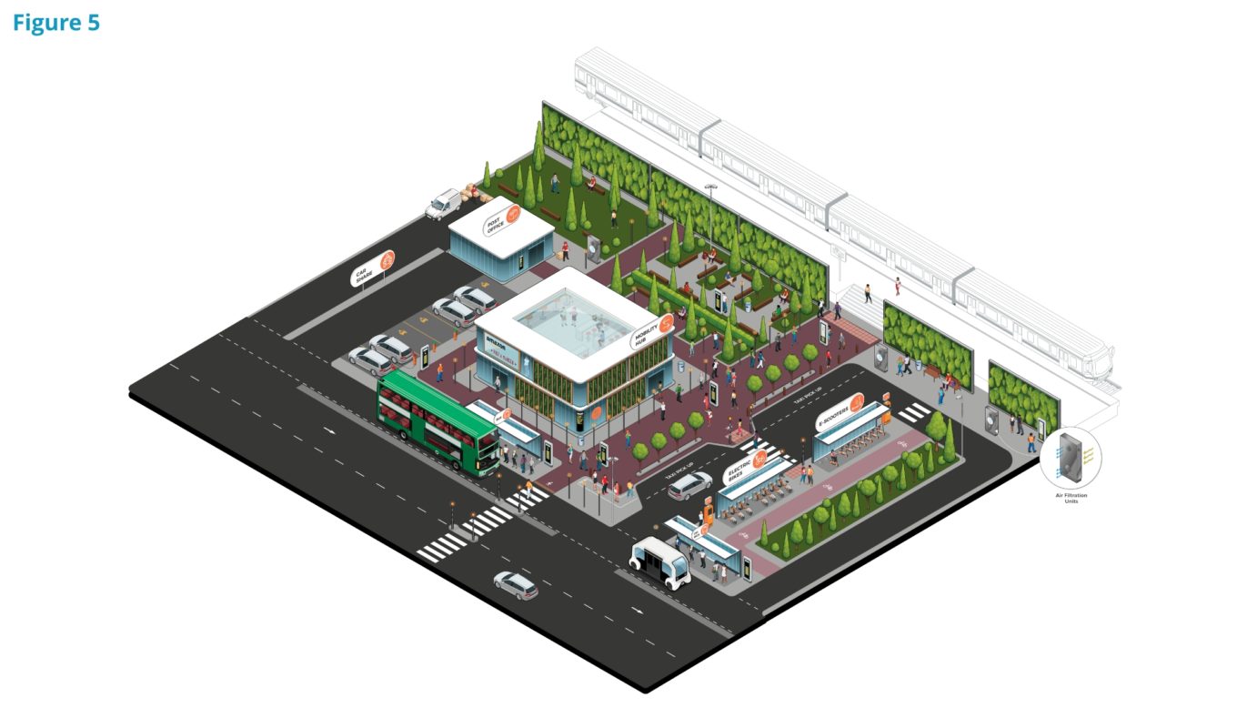
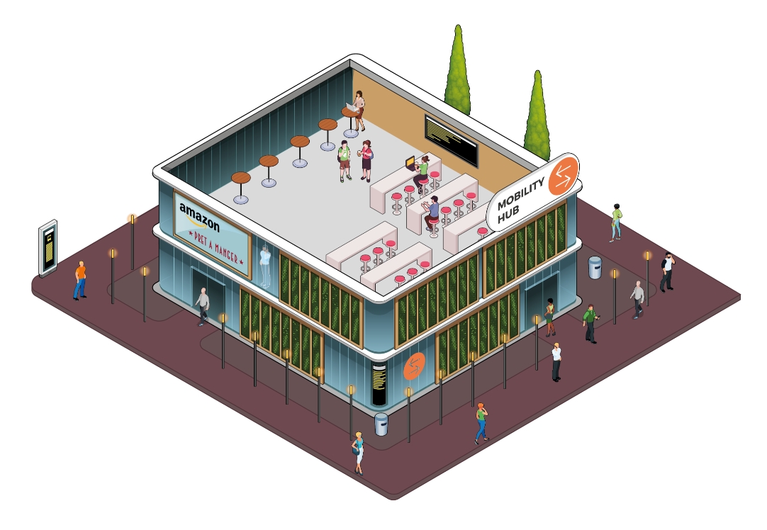
For Figure 5, the client approached us to visualise their new service offering; not only a transport solution in one place, but redesigning the urban space by connecting amenity areas around the ‘mobility hub’. This illustration was developed in close collaboration with the client and laid out in a way that allows parts of the image to be used independently in various outputs. At TDL we love making the most from our diagrams!
Conclusion
The isometric graphic is a powerful and attractive tool especially in information design. With careful planning, it can bring so much more to a project. Get in touch with us if you would like to discuss using isometric graphics for your projects.
1 – https://en.wikipedia.org/wiki/William_Farish_(chemist)
2 – https://en.wikipedia.org/wiki/Isometric_projection
If you enjoyed reading this blog post then you may enjoy our newsletter; TDL Quarterly! We will send you information on our team, latest projects and exciting initiatives every 3 months. You can sign up by clicking this link.